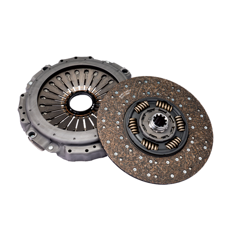
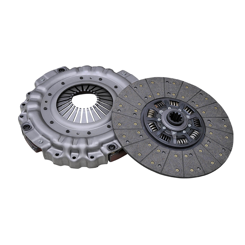
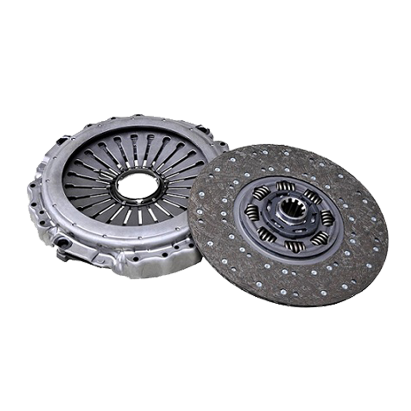
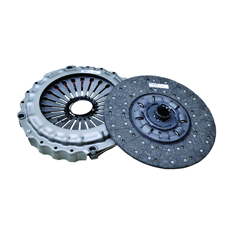
What are the key points in diagnosing the slippage of the 430 pull-type clutch assembly?
1. Symptom identification
430 When the pull-type clutch slips, a series of obvious symptoms will appear. During the vehicle's starting phase, even if the accelerator is pressed, the vehicle cannot start quickly and smoothly, showing a slow power transmission, and a feeling of "no power". During the acceleration process, the engine speed can increase rapidly, but the vehicle speed cannot increase rapidly at the same time. This is because the power generated by the engine is not effectively transmitted to the transmission system. In addition, the vehicle obviously feels insufficient power when climbing a slope. Even if the gear is downshifted and the accelerator is increased, it is still difficult to climb the slope, which seriously affects the vehicle's driving performance. In addition, during the clutch slippage process, due to frictional heat, you may also smell a burnt smell, which is an abnormal smell caused by excessive wear of the clutch plate.
2. Analysis of possible causes
l Friction plate wear : The friction plate is a key component for clutch transmission of power. After long-term use, the friction material on its surface will gradually wear out. When the wear reaches a certain extent, the thickness of the friction plate decreases, and the pressure between the friction plate and the pressure plate is insufficient, which will cause slippage. In addition, frequent sudden acceleration, sudden braking, or long-term use of the semi-clutch state will accelerate the wear of the friction plate.
l Failure of the pressure plate : The pressure plate transmits power by pressing the friction plate. If the pressure plate fails, such as the pressure plate spring is not elastic enough, deformed or broken, it cannot provide enough pressure to press the friction plate against the flywheel, causing the clutch to slip. In addition, wear and warping of the pressure plate surface can also lead to uneven pressure distribution and cause slippage.
l Release bearing failure : The release bearing plays a role in pushing the pressure plate to separate during the operation of the clutch. When the release bearing is stuck or severely worn, it will cause the release bearing and the pressure plate to not separate completely, so that the pressure plate cannot completely press the friction plate, and then slip.
l Failure of the clutch operating mechanism : If the clutch pedal has too little free travel or no free travel, the release bearing will always be pressed on the pressure plate, resulting in the pressure plate being unable to fully press the friction plate. Problems such as oil leakage and air ingress in the hydraulic operating system will result in insufficient hydraulic pressure and inability to push the clutch to work normally, all of which may cause the clutch to slip.
3. On-site detection method
l Road test : Conduct actual road tests to observe the vehicle's power performance when starting, accelerating, and climbing. If the above slipping symptoms occur, it is preliminarily judged that the clutch has a slipping problem.
l Check the clutch pedal free travel : Use a ruler to measure the clutch pedal free travel. Under normal circumstances, the 430 pull-type clutch pedal free travel should be within the specified range (usually 30 - 40mm). If the free travel is too small or there is no free travel, it needs to be adjusted.
l Check the thickness of the friction plate : Remove the clutch cover and use a caliper to measure the thickness of the friction plate. If the thickness of the friction plate is less than the specified limit value (the general wear limit is 2-3mm), the friction plate needs to be replaced.
l Check the pressure plate and flywheel : Observe whether the pressure plate surface is worn, warped or deformed, and check whether the pressure plate spring force is normal. At the same time, check whether the flywheel surface is flat. If there is wear or ablation, it should be repaired or replaced.
l Check the release bearing : Turn the release bearing to check whether it is flexible, stuck or making abnormal noise. If there is a problem with the release bearing, it should be replaced in time.
l Check the hydraulic control system : Check whether there is oil leakage in the hydraulic pipeline. If there is oil leakage, the pipeline needs to be repaired or replaced. Exhaust the hydraulic system to remove the air in the system and ensure that the hydraulic pressure is normal.
How to perform release bearing maintenance on 430 models
1. Bearing selection criteria
l Size matching : The size of the 430 release bearing must match the structure of the clutch, including key dimensions such as inner diameter, outer diameter and width. The inner diameter must fit tightly with the clutch release fork shaft, and the outer diameter must fit the contact area of the pressure plate release finger to ensure that it can work normally after installation without loosening or sticking.
l Load-bearing capacity : Select a release bearing with appropriate load-bearing capacity according to the vehicle's operating conditions and the clutch's workload. For vehicles that often operate under heavy loads and frequent gear shifting conditions, a release bearing with a stronger load-bearing capacity should be selected to ensure that it will not be damaged due to overload during long-term use.
l Material requirements : Release bearings are usually made of high-strength alloy steel or high-quality engineering plastics. Release bearings made of alloy steel have high strength and wear resistance and are suitable for harsh working conditions; release bearings made of engineering plastics have advantages such as light weight and low noise and are suitable for vehicles with high noise requirements. When selecting a release bearing, you should choose a release bearing of appropriate material according to the specific needs of the vehicle and the use environment.
l Brand and quality : Give priority to well-known brands and reliable quality release bearings. Well-known brands are more stringent in production process and quality control, which can guarantee product performance and service life. At the same time, pay attention to the product's quality certification and related test reports to ensure that the selected release bearings meet industry standards and usage requirements.
2. Lubrication cycle and operating specifications
l Lubrication cycle : The lubrication cycle of the 430 release bearing should be determined according to the frequency of use and working conditions of the vehicle. Generally, the release bearing should be lubricated and maintained every 20,000 to 30,000 kilometers or every 6 to 12 months. For vehicles that are frequently used and in harsh working conditions, the lubrication cycle should be appropriately shortened to ensure that the release bearing is always in a good lubrication state.
l Operation specification : When lubricating the release bearing, first remove the release bearing from the clutch. Use a special cleaning agent to clean the oil and impurities on the surface of the release bearing to ensure that the bearing surface is clean. Then, choose a suitable grease. It is generally recommended to use a high-temperature resistant and wear-resistant lithium-based grease. Apply the grease evenly to the ball, raceway and inner and outer ring surfaces of the release bearing to ensure that each part is fully lubricated. When applying the grease, be careful to avoid excessive application to prevent the grease from entering other parts of the clutch and affecting the normal operation of the clutch. Finally, install the lubricated release bearing back to the clutch according to the correct installation method, and debug it to ensure that the release bearing rotates flexibly without sticking.
3. Fault Tree Analysis of Abnormal Noise
l Bearing wear : After long-term use, the release bearing will have wear on the ball, raceway and other parts, causing the bearing to run unsteadily and produce abnormal noise. This noise usually appears as a "buzzing" or "rustling" sound, and increases with the increase of vehicle speed. When abnormal noise caused by bearing wear is found, the release bearing should be replaced in time.
l Poor lubrication : If the release bearing is not lubricated enough or the grease is deteriorated, the friction between the bearing components will increase, resulting in noise. This noise is usually a "squeaking" sound, which is more obvious when the vehicle starts or shifts gears. At this time, the release bearing needs to be relubricated or the grease needs to be replaced.
l Improper installation : During the installation of the release bearing, if the installation position is inaccurate, the installation force is uneven, or it interferes with other parts, abnormal noise will also be generated. For example, if the contact position between the release bearing and the release finger of the pressure plate is incorrect, it will cause uneven force on the bearing and produce abnormal noise. When installing the release bearing, you must strictly follow the installation specifications to ensure accurate installation.
l Clutch system failure : In addition to problems with the release bearing itself, failures in other clutch components may also cause abnormal noise from the release bearing. For example, uneven spring force on the pressure plate and uneven wear on the friction plate will cause vibrations when the clutch is working, which will then be transmitted to the release bearing and cause noise. When troubleshooting abnormal noise from the release bearing, it is also necessary to conduct a comprehensive inspection of the entire clutch system to find the root cause of the problem and repair it in a timely manner.
What should I do if the clutch pedal travel of this model is abnormal?
1. Standard process for draining the hydraulic system
l Preparation : Before draining the hydraulic system, you need to prepare the corresponding tools and materials, such as brake fluid, transparent hose, wrench, etc. At the same time, make sure the vehicle is on level ground and the engine is turned off.
l Locate the bleed bolt : The bleed bolt for the clutch hydraulic system on a 430 is usually located on the clutch slave cylinder. Once you have located the bleed bolt, place one end of a clear hose over the bleed bolt and the other end into a container to collect the drained brake fluid.
l Bleeding operation : Release the clutch pedal, then slowly depress the clutch pedal and keep it depressed. Use a wrench to loosen the bleed bolt 1/4 - 1/2 turn. At this time, the air will be discharged from the bleed bolt along with the brake fluid. Observe the flow of the brake fluid in the transparent hose. When there are no more bubbles in the brake fluid, quickly tighten the bleed bolt. Repeat the above operation until there are no bubbles in the discharged brake fluid. During the bleed process, pay attention to replenishing the brake fluid in time to prevent the brake fluid level from being too low.
l Check the fluid level : After the bleeding operation is completed, check the fluid level in the brake fluid reservoir to ensure that the fluid level is within the specified range. If the fluid level is too low, add brake fluid that meets the specified model.
2. Master cylinder push rod clearance measurement
l Disassemble related parts : In order to facilitate the measurement of the master cylinder push rod clearance, you need to first remove the decorative panel or protective cover near the clutch pedal to expose the clutch master cylinder push rod.
l Measuring the clearance : Use a feeler gauge to measure the clearance between the master cylinder push rod and the piston. When measuring, insert the feeler gauge between the push rod and the piston, and gently pull the feeler gauge. When you feel a slight resistance, the thickness of the feeler gauge is the push rod clearance. The master cylinder push rod clearance of the 430 model clutch is generally required to be between 0.5 and 1.0 mm. If the measured clearance is not within the specified range, it needs to be adjusted.
l Adjust the clearance : When adjusting the clearance of the master cylinder push rod, turn the adjustment nut on the push rod. If the clearance is too large, turn the adjustment nut clockwise to extend the push rod and reduce the clearance; if the clearance is too small, turn the adjustment nut counterclockwise to shorten the push rod and increase the clearance. During the adjustment process, use a feeler gauge to measure continuously until the clearance reaches the specified value.
3. Allowable tolerance range of travel
The standard value of the clutch pedal stroke of the 430 model is generally 150-160mm, and its allowable tolerance range is usually ±5mm. In other words, the clutch pedal stroke is within the normal range between 145-165mm. If the pedal stroke exceeds this range, it will affect the normal operation of the clutch, resulting in problems such as incomplete clutch separation or slippage. When the pedal stroke is found to be abnormal, it should be checked and adjusted according to the above-mentioned methods of venting the hydraulic system and adjusting the clearance of the master cylinder push rod to restore the pedal stroke to the normal range. At the same time, after adjusting the pedal stroke, an actual road test should be carried out to check whether the working performance of the clutch is normal to ensure the driving safety of the vehicle.
What are the process details that are easily overlooked during assembly installation?
1. Flywheel end face runout detection
l Preparation of testing tools : Before testing the end face runout of the flywheel, you need to prepare testing tools such as dial indicators and magnetic bases. Make sure that the accuracy of the testing tools meets the requirements and are in good working condition.
l Install the dial indicator : Fix the magnetic base on the engine body or other stable position, so that the measuring head of the dial indicator is vertically against the end face of the flywheel, and the contact point between the measuring head and the end face of the flywheel should be as close to the outer edge of the flywheel as possible.
l Detection operation : Slowly rotate the flywheel for one circle and observe the swing of the dial indicator pointer. The maximum swing value of the dial indicator pointer is the runout of the flywheel end face. The runout of the flywheel end face of the 430 model clutch is generally required to be no more than 0.05mm. If the test result exceeds the specified value, it means that the flywheel end face has problems such as warping and deformation, and the flywheel needs to be repaired or replaced. The repaired flywheel also needs to be re-tested for end face runout to ensure that it meets the installation requirements.
2. Specifications for the use of centering and positioning tools
l Choose the right centering tool : When installing the 430 clutch assembly, a dedicated centering tool should be used. The size and shape of the centering tool should match the structure of the clutch to ensure that the various components of the clutch can be accurately aligned.
l Install the centering tool : Before installing the clutch pressure plate and friction plate, insert the centering tool into the center hole of the flywheel and the hole of the transmission input shaft. Then install the friction plate and pressure plate in sequence so that the center holes of the friction plate and pressure plate fit tightly with the centering tool. During the installation process, pay attention to keep the position of the centering tool stable to avoid deviation.
l Check the centering effect : After installing the clutch pressure plate and friction plate, check whether the centering tool can rotate smoothly and whether the position of the friction plate and pressure plate on the flywheel is even and symmetrical. If the centering effect is not satisfactory, you need to readjust the position of the centering tool until you achieve a satisfactory centering effect. Finally, take out the centering tool before installing the transmission.
3. Bolt tightening sequence
l Determine the bolt tightening sequence : The bolts on the 430 clutch pressure plate are usually distributed in a circle. When tightening the bolts, they should be tightened in the order of diagonal crossing. This will make the pressure plate evenly stressed and avoid deformation of the pressure plate due to uneven stress.
l Tighten bolts in stages : The tightening process of bolts is divided into multiple stages, generally 2-3 stages. In the first stage, use a wrench to initially tighten the bolts so that the pressure plate and the flywheel are initially fitted, but do not tighten them completely; in the second stage, tighten the bolts to 50%-60% of the specified torque in the order of diagonal crossing; in the third stage, tighten the bolts to the specified torque value (generally 80-100N・m, refer to the vehicle maintenance manual for specific values) again in the order of diagonal crossing. In the process of tightening the bolts, use a torque wrench to ensure that the tightening torque of each bolt meets the specified requirements. At the same time, after tightening all the bolts, check the tightening of the bolts again to prevent loosening.
 English
 русский
 English
  No.25, Hu Chuang Road, New District Industrial Park, Suzhou, Jiangsu, China.
  +86-13338663262
