Within the realm of mechanical power transmission, particularly in applications requiring the engagement and disengagement of rotational force, the clutch assembly stands as a critical component. The term “420 clutch assembly” refers to a specific design and size classification common within certain industries.
The designation “420” typically corresponds to a specific size and set of performance characteristics within a product numbering system. It indicates the physical dimensions, torque capacity, and general specifications of the assembly. A 420 clutch assembly is generally considered a medium-duty component, often found in industrial machinery, agricultural equipment, and other mechanical systems where controlled power transfer is essential. Its primary function is to connect a driving shaft, such as one from an engine or motor, to a driven shaft, like the input shaft of a transmission, and to do so in a smooth and controllable manner. The ability to interrupt power flow without stopping the prime mover is a fundamental requirement in many machines, and the 420 clutch assembly is engineered to meet this need reliably.
The Core Components and Their Roles
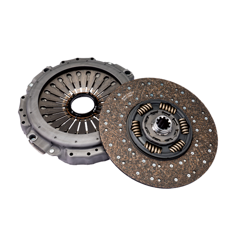
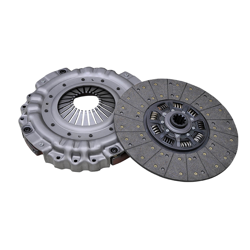
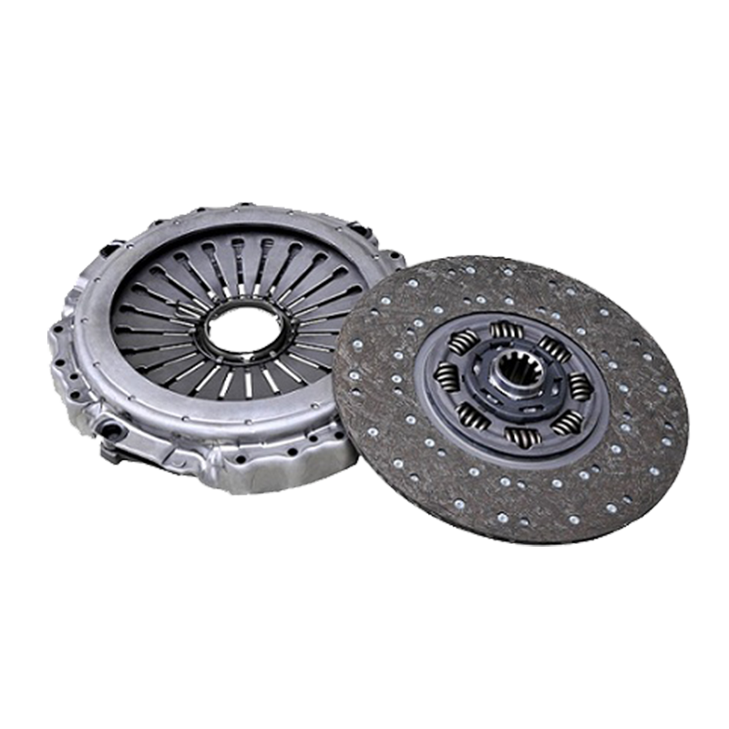
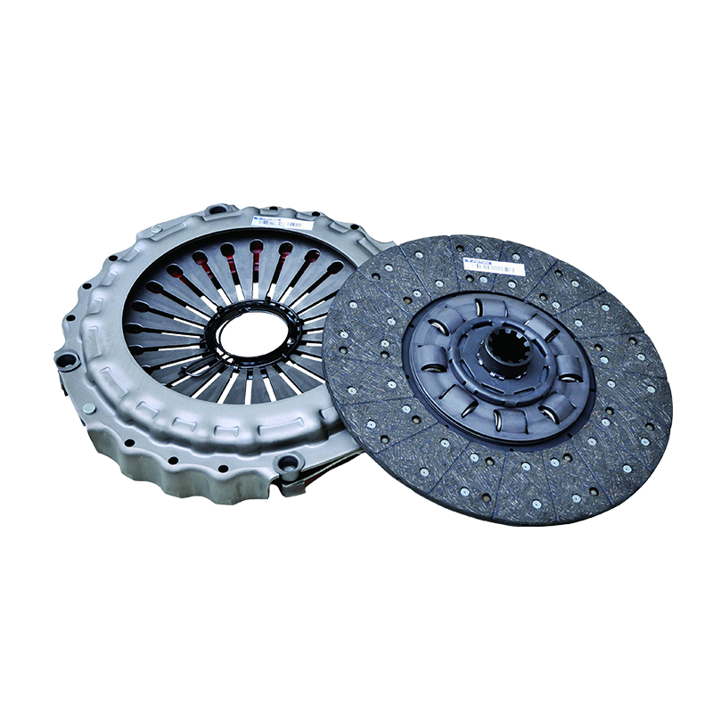
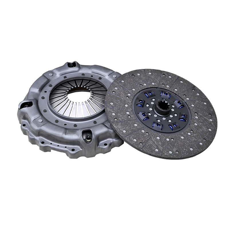
A 420 clutch assembly is not a single monolithic part but rather a carefully integrated system of components, each serving a distinct purpose. Understanding these individual parts is key to comprehending the assembly’s overall function. The main constituents typically include the clutch drum, the hub, the driven discs, the drive discs, pressure plates, springs, and a throw-out mechanism.
The clutch drum is the outer housing that rotates with the driving force. It is usually bolted directly to the engine’s flywheel or another source of rotational power. Inside this drum resides the hub, which is splined to the driven shaft. This splined connection allows the hub to slide axially along the shaft while still rotating with it. The actual transfer of torque occurs through a series of interleaved discs. The driven discs, often lined with a high-friction material, are keyed to the hub. Alternating with these are the drive discs, which are typically made of steel and are keyed to the inside of the clutch drum.
The force required to clamp these discs together is supplied by springs and pressure plates. One or more pressure plates are used to apply a compressive force on the stack of discs. Springs, which can be coil springs arranged in a circle or a single diaphragm spring, provide this clamping force. When the clutch is engaged, these springs push the pressure plate against the disc pack, creating significant friction. This friction locks the drum and the hub together, causing them to rotate as a single unit and thereby transmitting power from the driving shaft to the driven shaft. The throw-out bearing and mechanism are the components responsible for disengagement. When the operator actuates the clutch control, the throw-out bearing moves forward and presses against the springs. This action relieves the pressure on the disc pack, separating the drive and driven discs. With the friction connection broken, the drum can continue to spin independently of the hub, and power transmission ceases.
The Principle of Operation: Engagement and Disengagement
The operation of a 420 clutch assembly is a straightforward application of friction principles, though its execution is precision-engineered. The cycle of engagement and disengagement is fundamental to its purpose.
When the clutch is in its default, engaged state, the spring force maintains full pressure on the disc pack. The friction between the alternating drive and driven discs is sufficient to prevent slippage under the designed torque load. The entire assembly—drum, discs, hub, and pressure plate—rotates synchronously. This is the state for normal power transmission, where rotational speed and torque are transferred efficiently from the power source to the driven equipment.
Disengagement is initiated by the operator or an automated control system. Actuating the clutch pedal or lever moves the throw-out bearing. This bearing contacts the pressure plate’s release fingers or the spring mechanism itself. As force is applied against the springs, the pressure plate retracts. This retraction creates a small but critical gap between the drive and driven discs. With the compressive force removed, the friction between the discs drops to near zero. The driving element (the drum and drive discs) continues to rotate with the engine, while the driven element (the hub and driven discs) can either remain stationary or slow down, effectively decoupling the driven machinery from the power source. This allows for gear changes in a transmission or the complete stopping of a machine’s function while the engine continues to run.
Re-engagement is the reverse process. As the operator releases the clutch control, the spring force gradually reapplies pressure to the disc pack. The discs begin to make contact, and friction builds. Initially, there is slippage as the rotational speeds of the driving and driven components synchronize. This slippage must be controlled; too abrupt an engagement causes jerking and excessive wear, while too gradual engagement leads to prolonged slippage and heat generation. A well-designed 420 clutch assembly, in proper working order, allows for a smooth transition from slippage to full, lock-step rotation, enabling seamless power resumption.
Key Performance Characteristics and Selection Criteria
Selecting the appropriate 420 clutch assembly for a given application requires careful consideration of several performance parameters. An incorrect selection can lead to premature failure, inefficient operation, or an inability to handle the required loads.
The single most important factor is torque capacity. The clutch must be rated to transmit the maximum torque produced by the engine or motor without slipping. Exceeding this rating will cause accelerated wear and eventual failure. The torque capacity of a 420 clutch assembly is a function of several design elements: the number of friction surfaces (determined by the number of discs), the effective radius of the disc pack, the coefficient of friction of the disc material, and the force applied by the springs. It is crucial to choose an assembly whose rated torque provides a sufficient safety margin above the application’s peak torque demand.
Another critical consideration is heat dissipation. During engagement, especially if it is prolonged, and during any slippage, a significant amount of heat is generated. This heat must be effectively dissipated to prevent damage to the friction material, warping of metal components, and degradation of lubricants. Some assemblies are designed for dry operation, while others are meant to run in an oil bath. An oil-bath clutch, often referred to as a wet clutch, offers superior cooling and can handle more frequent engagement cycles and higher slippage heat, but it may have a different friction profile. The operating environment dictates whether a dry or wet 420 clutch assembly is suitable.
Durability and service life are also paramount. This is influenced by the quality of materials used for the friction surfaces and metal components. High-quality, sintered bronze or carbon composite friction materials offer excellent wear resistance and consistent performance under high temperatures. The design of the damping mechanisms, often integrated into the hub assembly to absorb torsional vibrations, also contributes to longevity by protecting the drivetrain from shock loads.
| Consideration | Description | Impact on Selection |
|---|---|---|
| Torque Capacity | The maximum torque the clutch can transmit without slipping. | Must exceed the application’s peak torque with a safety margin. |
| Heat Dissipation | The ability to manage heat generated during engagement and slippage. | Determines choice between dry (air-cooled) and wet (oil-bath) designs. |
| Engagement Cycle | How frequently the clutch is engaged and disengaged. | High-cycle applications require robust designs with superior cooling. |
| Size & Packaging | The physical dimensions and mounting specifications. | Must fit within the constraints of the existing machinery design. |
| Damping Features | Elements that absorb torsional vibrations from the engine. | Crucial for protecting downstream components from shock loads. |
Maintenance, Wear, and Common Issues
Like all mechanical systems, a 420 clutch assembly is subject to wear and requires periodic inspection and maintenance to ensure optimal performance and longevity. The most common form of wear affects the friction discs. Over time, the friction material on the driven discs gradually wears away. This wear is accelerated by improper operation, such as “riding the clutch” (keeping it partially engaged) or excessive slippage during engagement. As the material wears, the springs must extend further to maintain clamping pressure. Eventually, the springs reach their maximum extension, and clamping force diminishes, leading to clutch slippage even when fully engaged. This slippage generates intense heat and quickly destroys the assembly.
Another common issue involves the release mechanism. The throw-out bearing is a component that experiences high loads only during disengagement. However, if it fails, it can prevent the clutch from disengaging fully, making gear shifts difficult or impossible. Contamination is a severe problem, especially for dry clutches. Oil leaking from the engine onto the clutch disc surfaces drastically reduces the coefficient of friction, causing severe slippage and rapid failure. For wet clutches, the quality and level of the oil are critical; degraded or incorrect oil can lead to poor clutch performance and wear.
Routine maintenance primarily involves inspection and adjustment. The clutch pedal or lever often has a free-play adjustment. This free play represents the clearance between the throw-out bearing and the pressure plate fingers when the clutch is engaged. Maintaining correct free play is essential. Too little free play can keep the bearing in constant contact, leading to premature wear and potential slippage from incomplete spring pressure. Too much free play can prevent full disengagement, as the throw-out mechanism cannot fully compress the springs. In oil-bath systems, regular oil changes according to specifications are non-negotiable for preserving the life of the 420 clutch assembly.
The 420 clutch assembly is a quintessential example of precision mechanical engineering, fulfilling the vital role of managing power transmission in a wide array of machinery. Its operation, based on the controlled application of frictional force, is simple in concept but complex in its execution, requiring robust materials, exacting tolerances, and thoughtful design. From its core components—the discs, hub, drum, and pressure plate—to its critical performance characteristics like torque capacity and heat dissipation, every aspect is engineered for reliability and efficiency.
Understanding the principles behind its engagement and disengagement cycle provides insight into its fundamental importance in mechanical systems. Furthermore, recognizing the key criteria for its selection and the common issues that affect its service life empowers operators and maintenance personnel to ensure its continued reliable operation. Proper installation, regular adjustment of free play, and vigilance against contamination are all practices that significantly extend the functional life of a 420 clutch assembly. As a fundamental component in power transmission, its effective function remains indispensable, highlighting the enduring importance of well-designed mechanical systems in an increasingly digital world.
 English
 русский
 English
  No.25, Hu Chuang Road, New District Industrial Park, Suzhou, Jiangsu, China.
  +86-13338663262
